In-house PSA sorbent: reaction set-up and lab room
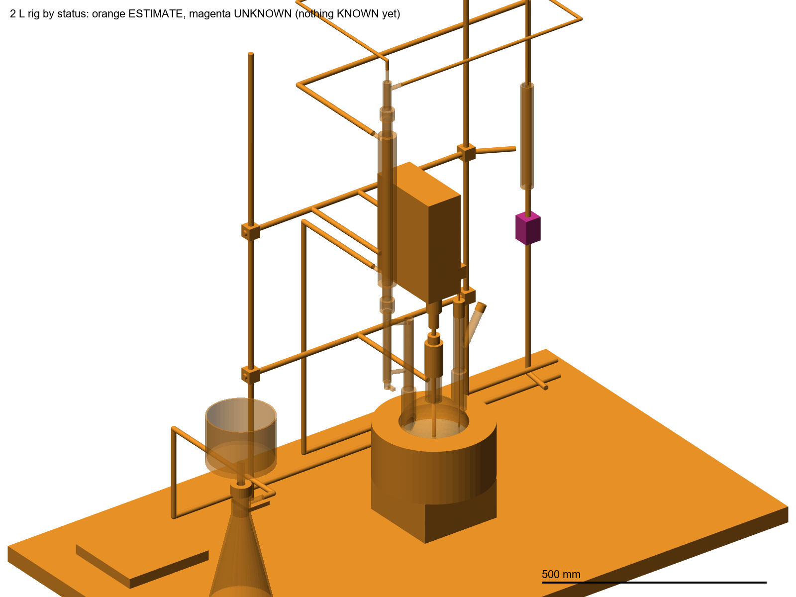
The grafting rig and a one-room lab of about 14 m² for making primary–secondary amine (PSA) silica for QuEChERS cleanup. It follows the project plan and SOP Draft rev 0 (with the rev 1 changes). These are concept models with checks, not construction drawings. No supplier drawings were available, so every dimension is a catalogue-typical estimate and the items with no product chosen yet are unknown.
Room 4.0 × 3.5 m = 14 m², 2.8 m ceiling (assumed) Trial batch: 2 L flask, ≤75 g silica Scale-up: 3 L flask, 100 g3D models
How PSA is made
Commercial PSA (Agilent Bondesil-PSA, Biotage ISOLUTE PSA) is irregular silica, 40–63 µm, 60 Å, ~500 m²/g, with N-(2-aminoethyl)-3-aminopropyl groups bonded to it. The groups are a free base and the silica is not endcapped. The plan makes it the usual way. N-[3-(trimethoxysilyl)propyl]ethylenediamine (CAS 1760-24-3) condenses with the surface silanols of dried silica in refluxing dry toluene under N₂, and methanol comes off. A trialkoxysilane also cross-links with itself through trace water, so the bonded layer is polymeric, like the commercial benchmark.
≡Si–OH + (MeO)₃Si–(CH₂)₃–NH–(CH₂)₂–NH₂ → ≡Si–O–Si(OMe)₂–(CH₂)₃–NH–(CH₂)₂–NH₂ + MeOH
Water is the main thing to control. It makes the silane polymerise in solution (gel, lumps) instead of on the surface. That is why the plan uses activated silica, sieve-dried toluene at ≤50 ppm water by KF, a Dean-Stark step and N₂ throughout. An overhead PTFE paddle is used instead of a stir bar, because a bar grinds the particles into fines.
- A. Pre-treat: optional 1 M HCl wash at 80 °C for 4 h (recommended for this silica), rinsed to <10 µS/cm. Fines are removed by settling (2 min per cm of depth, ≥3 cycles). Activate at 150 °C.
- B. Set up and dry: charge silica and dry toluene, then reflux for 2 h through the Dean-Stark trap. Toluene KF ≤50 ppm before continuing.
- C. Silanise: add the silane through the septum at ~80 °C under N₂ (default 2.5 mmol/g; the pilot fixes the dose), then reflux at ~110 °C for 16 h at 150–250 rpm.
- D. Work-up: filter at ≤40 °C on a G4 frit (G3 only after verified fines removal). Wash with toluene ×2, methanol ×3 (optional MeOH:H₂O), then methanol ×2, at ≥5 mL/g per wash. No acetone, ketones or chlorinated solvents.
- E. Dry and cure: pre-dry the cake in the hood under N₂ until free-flowing, then vacuum oven at 40–50 °C → 110 °C for ≥12 h. Break the vacuum with N₂.
- F–H: sieve 38–75 µm in an extracted enclosure. Pack in amber glass under N₂. QC: %N 2.80–3.50 (1.00–1.25 mmol/g), titration ≥90 % of a commercial reference lot, and functional tests per SANTE/11312/2021.
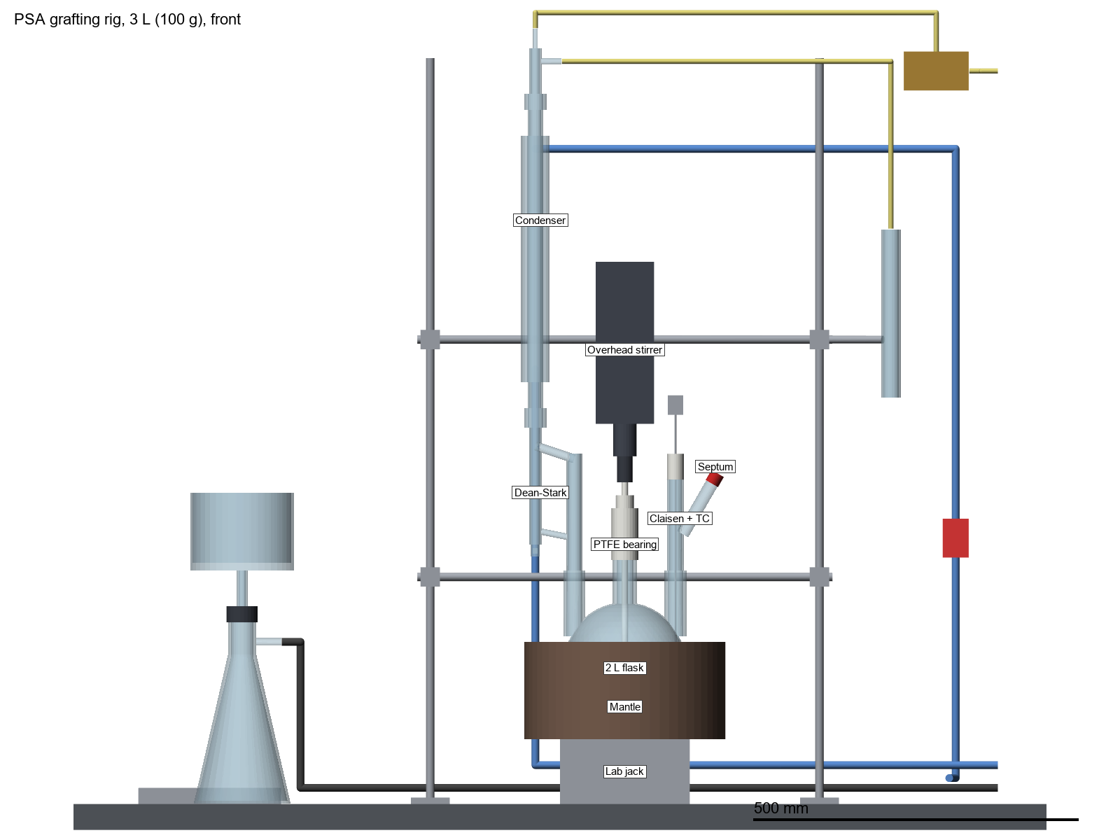
Batch sizes in the models: 2 L flask, 75 g silica + 0.80 L toluene + 41 mL silane = 0.87 L slurry (44 % fill). 3 L flask, 100 g + 1.10 L + 54 mL = 1.20 L (40 % fill). Both are within the plan's ≤50 % fill rule.
Reaction set-up
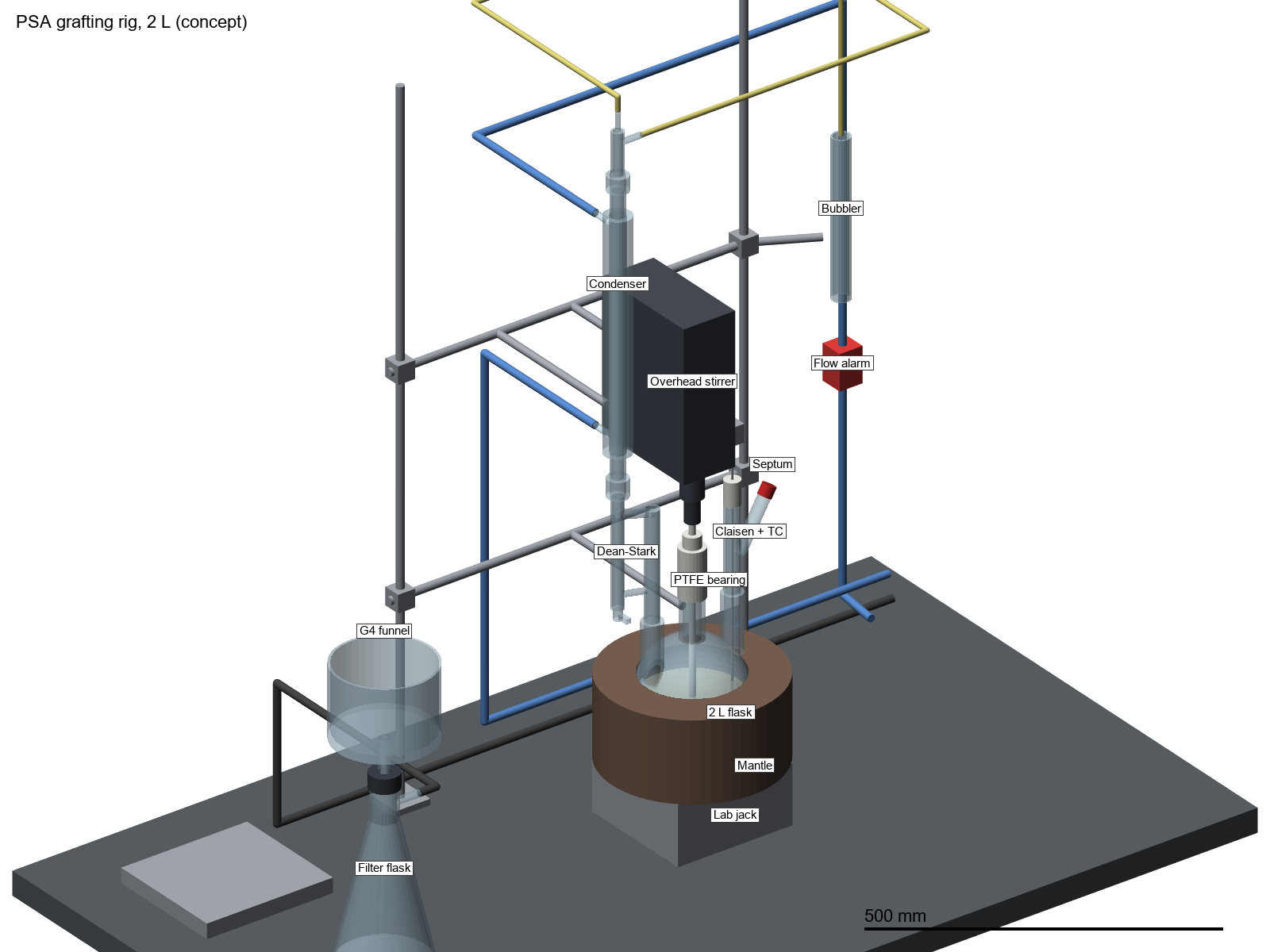
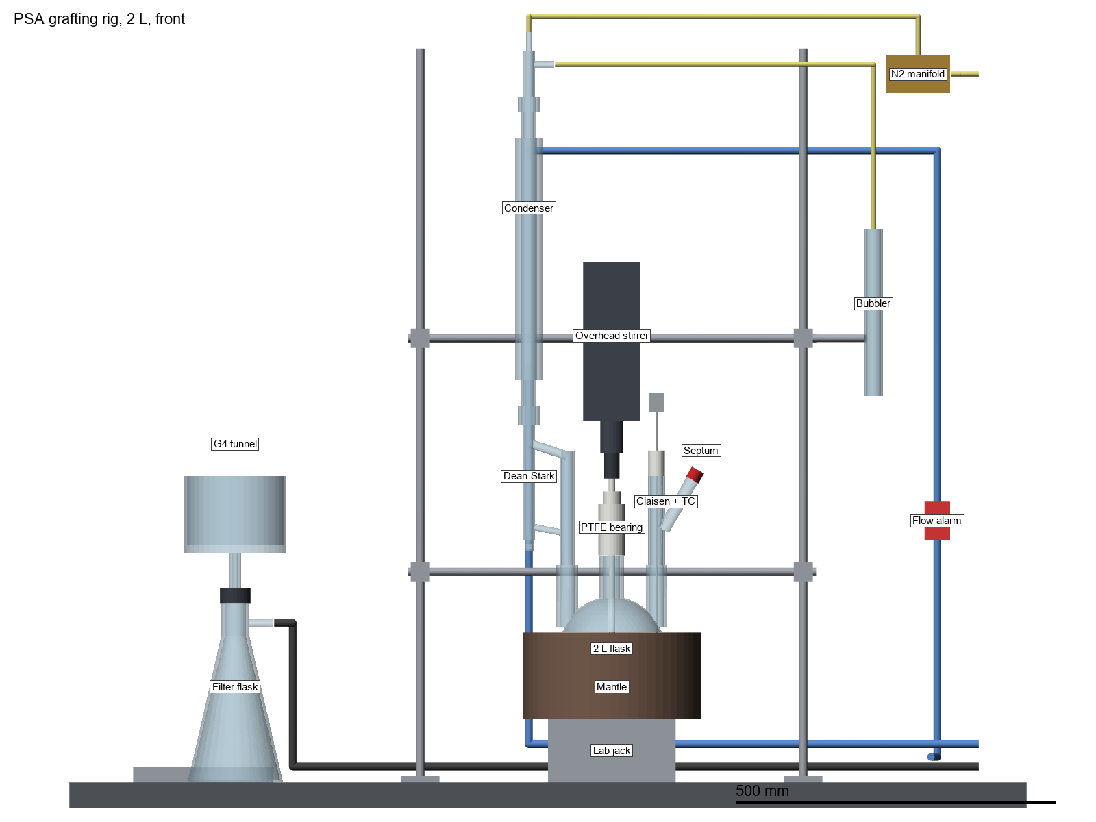
Everything wet or hot is inside a 1.5 m ducted fume hood, on a rigid two-rod lattice. The flask sits in its mantle on a lab jack, so lowering the jack is the quick way to cut the heat.
- Centre neck: gas-tight PTFE bearing, PTFE shaft and half-moon paddle, overhead stirrer at 150–250 rpm.
- Left neck: Dean-Stark trap (25–50 mL, stopcock), then a 400 mm water condenser, then the N₂ T-piece. Gas comes in on top and the side arm goes to an oil bubbler, so the system is always open.
- Right neck: Claisen adapter. The straight arm carries the K-type thermocouple through a PTFE gland (internal temperature for the mantle controller). The angled arm carries the septum for the silane syringe.
- Safety: an independent manual-reset over-temperature cutoff with its own sensor in the mantle. Both controllers sit outside the hood. A flow alarm on the condenser return line is required for any unattended reflux.
- Work-up station, left half of the hood: 2 L heavy-wall filter flask with a ~150 mm sintered funnel. The vacuum line runs through the hood side port to the cold trap and the diaphragm pump (pump exhaust back to the hood). The pre-dry tray sits behind it.
Room layout (≈14 m²)
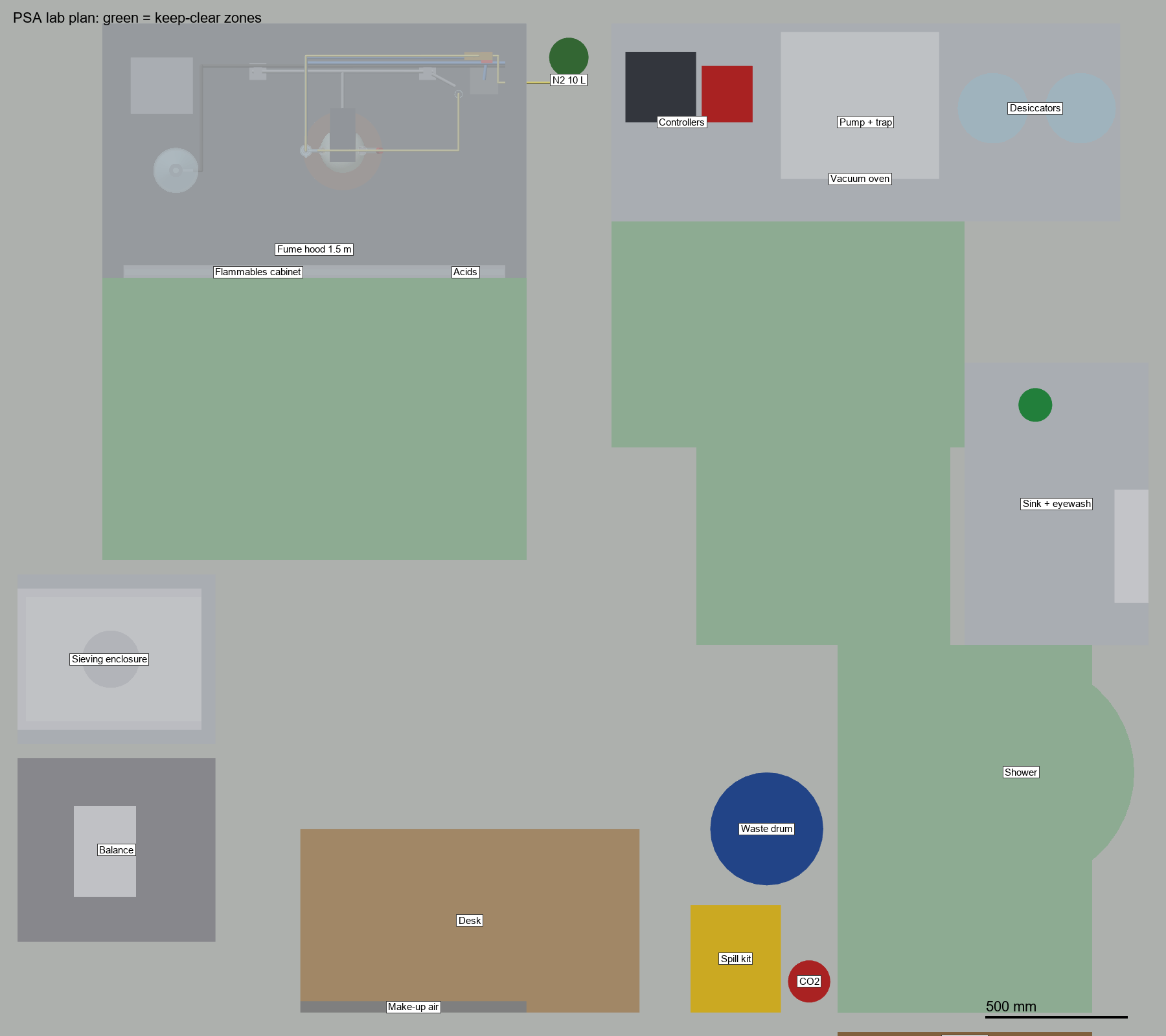
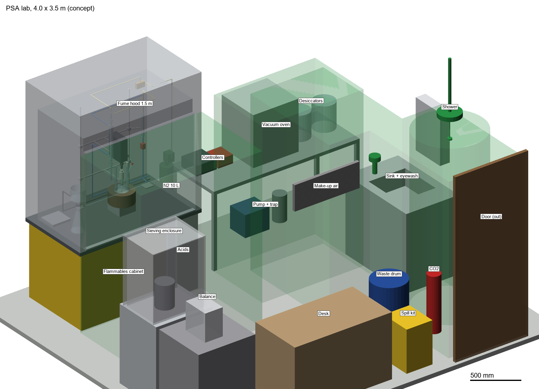
The plan's "circa 10–15 m²" is taken as a 4.0 × 3.5 m room with a 2.8 m ceiling (39 m³). The hood is on the north wall, as far from the door as the room allows, so people walking past don't disturb the airflow at its face.
- North wall: 1.5 m hood above an EN 14470-1 flammables cabinet (toluene, methanol, silane, two 10 L non-halogenated waste cans) and a separate small acid cabinet for the HCl. Next to it, a 10 L N₂ cylinder chained to the wall. Then a 1.8 m bench with the mantle controller, the over-temperature cutoff, the single vacuum oven (plan option 6.4) and two desiccators. The pump and cold trap go under the bench.
- West wall: anti-vibration balance table, 2 m from the hood face. An extracted enclosure for dry-powder work and sieving.
- East wall: sink with DI water and a plumbed eyewash.
- South wall: an outward-opening 900 mm door with the safety shower inside it. CO₂ extinguisher, spill kit and solid hazardous-waste drum by the door. The records desk (clean zone) and the high-level make-up air grille, 2.6 m from the hood face.
- Keep-clear zones (green): 1.0 m in front of the hood, a 900 mm route from the hood to the door, the shower standing area, and standing room at the oven bench. The checks confirm that nothing sits in them.
What the checks found
1. A rigid half-moon paddle will not go through the NS 29/32 centre neck
The neck bore is about 26 mm. The paddle needed is about 90 mm wide in the 2 L flask and 100 mm in the 3 L. Order the PTFE stirrer (a hard-to-source, tier-A item) with a hinged/folding or screw-on blade, or choose flasks with an NS 45/40 centre neck and a matching bearing. Decide before the stirrer bearing and paddle quotes go out.
2. The hood's interior height decides whether the rig fits
Assuming 1,250 mm of clear height above the worksurface, the 2 L rig has 46 mm to spare and the 3 L rig only 26 mm (fails the 40 mm criterion). The highest point is the N₂ line looping over the T-piece. Bringing N₂ in at the side of the T-piece gains about 30 mm; lowering the jack 25 mm also works. Put "≥1,250 mm interior height" in the hood specification, and dry-assemble the full stack before the first reflux.
3. The room needs a dedicated make-up air supply
A 1.5 m hood at a 500 mm sash opening and 0.5 m/s draws about 1,215 m³/h. With the sieving enclosure (~300 m³/h) the total is ~1,500 m³/h, about 39 air changes per hour in a 39 m³ room. A door undercut cannot supply that. Fit a low-velocity supply terminal well away from the hood face. The modelled 0.8 × 0.3 m grille would run at 1.75 m/s, so make it larger or use a diffuser, and plan for heating that air in winter. EN 14175-3 type tests use a room of at least 4 × 4 m, so ask for an EN 14175-4 on-site test once the hood is installed in this smaller room.
4. Use a small N₂ cylinder in a room this size
Worst case: the whole cylinder is released with the ventilation off, into 34.7 m³ of free air. A 10 L (200 bar, ~1.9 m³ gas) leaves 19.8 % O₂, which is acceptable. A 20 L leaves 18.7 % and a 50 L 15.3 %, both below 19.5 %. Keep a 10 L cylinder in the room, or put a larger one outside with a fixed line. Fit an O₂ monitor if a larger cylinder or argon is ever brought inside.
5. Margins that are fine but thin
In the 2 L run the paddle is 14 mm under the slurry surface and the thermocouple tip 21 mm, so don't cut the toluene charge. The paddle sweep clears the glass by 10 mm and the thermocouple by 24 mm. The rig stands 270 mm behind the sash (≥150 mm is required).
6. What passes
No clashes between parts, in the rig or in the room. Nothing in the keep-clear zones. Eyewash 2.6 m and shower 3.9 m from the hood operator (≤10 s). Balance 2.0 m and door 3.0 m from the hood face. Both flasks ≤50 % full. All controller electronics outside the vapour zone.
Check results
| Model | Check | Result |
|---|
The checks use exact OCC boolean volumes and shape distances from the cad-loop toolchain, not bounding boxes. Intended contacts are listed as interfaces: the cutoff sensor in the mantle, and the flow switch on its hose. The raw numbers are in checks_psa.json.
Assumptions to confirm
| Item | Assumed | Why it matters |
|---|---|---|
| Room | 4.0 × 3.5 × 2.8 m, door in the short wall | Ventilation rate, O₂ calculation, layout |
| Fume hood | 1.5 m, interior 1,350 × 750 × 1,250 mm, worksurface at 900 mm | Rig headroom (finding 2), exhaust flow (finding 3) |
| Flasks | 2 L OD 166 mm, 3 L OD 186 mm, parallel NS 29/32 side necks 70/78 mm off the axis | Angled side necks move the Dean-Stark and condenser outwards |
| Overhead stirrer | RW 20 class, body 90 × 190 × 250 mm | Stack height and clamping |
| Vacuum oven | 15 L class, 560 × 520 × 600 mm on the bench | Bench length |
| Sieving enclosure, cutoff unit, flow alarm, make-up terminal | Placeholders (unknown) | No product chosen yet |